
- 4E, No.3 Shenfeng Road, Liuyao Community, Henggang Street, Longgang District, Shenzhen,China
- cc.shen@xypltd.com
- Call: +86 15112667855
News
Using built-in filters to improve the testing performance of low-cost signal sources
- 2026-08-18
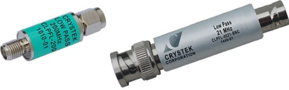
If pure string waves are required during testing, but only arbitrary function generators with high harmonic levels can be used, how should they be handled? If you are mixing the output signals of two signal generators and need to select the upper sideband component at the output of the mixer. How can we achieve this? The solution is to use built-in RF filters, such as Crystek Corporation CLPFL-0200 with SMA connector (Figure 1, left) and CLPFL-0021-BNC with BNC · connector (Figure 1, right).
Figure 1: Built in coaxial filters, such as CLPFL-0200 with SMA connector (left) or CLPFL-0021 with BNC connector (right), can reduce signal harmonics and noise on the signal source. (Image source: Crystek Corporation)
By selectively attenuating unwanted frequencies and transmitting desired frequency components, RF filters can purify signals. The built-in filter is suitable for coaxial lines, with a nominal impedance of 50 ohms (Ω). This type of filter reduces noise by reducing signal bandwidth and can also control the signal spectrum to reduce harmonics, images, and interference signals.
Types of Filters
The built-in filter has multiple configuration types, including low-pass filter, high pass filter, and band-pass filter (Figure 2).
Figure 2: The frequency response of low-pass, high pass, and band-pass filters is shown. (Image source: Art Pini)
A low-pass filter allows frequencies below a fixed cutoff frequency to pass through and eliminates signal harmonics with a cutoff frequency slightly above the fundamental frequency. A high pass filter allows frequencies above a fixed cutoff frequency to pass through and eliminates interference signals with cutoff frequencies higher than the power line frequency. A bandpass filter can attenuate unwanted signals by using frequencies within the desired frequency band and serve as a pre selection filter for the RF front-end. The area with less signal transmission loss is called passband, and the area with greater signal attenuation is called stopband. The region between the passband and stopband is the transition zone (transition band).
Choose the correct filter
Filters are designed for specific frequency response characteristics, including the sharpness of the transition from passband to stopband, the flatness of passband and stopband, and the phase response as a function of frequency. Figure 3 shows several classic designs.