
- 4E, No.3 Shenfeng Road, Liuyao Community, Henggang Street, Longgang District, Shenzhen,China
- cc.shen@xypltd.com
- Call: +86 15112667855
News
Understand the role of drivers, switches, and laser diodes in achieving effective lidar performance
- 2026-09-04
Lidar systems have become the preferred method for cars, automated guided vehicles (AGVs), and even robotic vacuum cleaners to "observe" their surrounding environment. Drones and aircraft flying at higher altitudes also use LiDAR navigation to draw terrain maps at greater distances.
Despite in-depth research on LiDAR, designers must be very cautious when selecting key components required for generating light pulses, such as gate drivers, gate switch FETs, and laser diodes.
This article first provides an overview of LiDAR, then introduces examples of key electro-optical components and demonstrates how these components work together to generate the necessary pulses.
Working principle of LiDAR
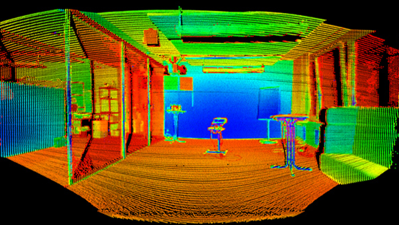
The working principle of LiDAR is to continuously emit short beam pulses of medium power, and then capture their reflections. It establishes a point cloud of the surrounding environment by measuring time of flight (ToF), presenting a three-dimensional (3D) perspective (Figure 1). Many systems use multiple laser diodes to form a matrix to expand coverage.
Establishing point cloud images using LiDAR method
Figure 1: Lidar can establish point clouds for 3D rendering of the surrounding environment. (Image source: Blickfeld GmbH)
The application determines the performance of the laser radar system. Compared to systems used for cars, systems for slow-moving, area limited floor cleaning robots or AGVs have much looser requirements for range and angular resolution, as cars must travel at faster speeds and respond to vehicles, riders, or pedestrians. The highest performance target for automotive applications is typically an effective range of 100 to 200 meters with an angular resolution of 0.1 °.
The dual axis electromechanical galvanometer scans the entire image area with laser flashes to obtain accurate point clouds. Due to the ability of LiDAR systems to measure the ToF of each emitted pulse and its associated echo, 3D images with deep perspective can be established for precise navigation of vehicles in the surrounding environment.
The electronic optical path of the core of LiDAR
A complete LiDAR system, such as the one used in AGVs, requires various interconnected optical, analog, processor, and mechanical modules. The core of this system is the electronic optical path, which consists of a laser light source and a co working optical receiver (Figure 2).
Image of electro-optical signal path and related components (click to enlarge)
Figure 2: The electro-optical signal path and related components are the core of the LiDAR system (middle row on the right). (Image source: ROHM)
The signal path of the light source that generates the light pulse stream is controlled by a dedicated microcontroller (MCU), which determines the required repetition rate and width of the light pulses. The light source path has three key functional elements:
The gate driver provides high-speed pulses with fast rise and fall times to turn on and off the gate switch.
The gate switch FET is very sensitive and can control the current of the laser diode.
Laser diodes generate independent, non overlapping light pulses at the desired wavelength.
Selecting and integrating these components requires an understanding of electrical issues as well as optical characteristics such as field of view, laser diode power and wavelength angle sensitivity, and signal-to-noise ratio (SNR). Advanced software algorithms can overcome some limitations in the electronic optical signal path and challenges in the sensed environment. However, for caution, engineering design should choose components optimized for LiDAR, rather than assuming that these algorithms can compensate for deficiencies.
By studying the representative components of each of the above functions, we can understand how devices optimized by LiDAR cope with many challenges:
gate driver
ROHM Semiconductor BD2311NVX-LBE2 (Figure 3) is a single channel, ultra high speed GaN gate driver that is highly suitable for industrial applications such as AGVs. It provides the necessary combination of driving current and voltage. It adopts a 6-pin package, with a size of only 2.0 mm × 2.0 mm × 0.6 mm, an output current of up to 5.4 A, and a power supply voltage range of 4.5 V to 5.5 V.