
- 4E, No.3 Shenfeng Road, Liuyao Community, Henggang Street, Longgang District, Shenzhen,China
- cc.shen@xypltd.com
- Call: +86 15112667855
News
Integrated time to digital converter simplifies the design of time-of-flight ranging applications
- 2026-10-10
A time to digital converter (TDC) is an electronic device that accurately measures the time between a starting pulse and one or more stopping pulses. They integrate all necessary functions of electronic stopwatches, greatly simplifying the measurement of Time of Flight (ToF) in various applications. These functions are the basic features of distance measurement applications.
For example, in an ultrasonic rangefinder, the time between the emitted ultrasonic pulse and the echo received from the target (Figure 1) is proportional to the distance between the transmitter and the target.
Figure 1: The ultrasonic rangefinder measures the time between the emitted pulse group (left) and the received target reflected pulse group (right) to determine their distance. (Image source: Art Pini)
The transmitted pulse propagates to the target, reflects back, and is sensed by the sensor. In the example shown above, the round-trip travel took 3.5 milliseconds (ms), so the time for the ultrasound pulse to propagate back from the target is 1.75 ms. At 22 ° C, the sound wave velocity is 344 meters per second (m/s), so the distance is 0.00175 x 344=0.6 m.
Similar applications that use distance measurement include radar, light detection and ranging (LiDAR), and sonar, which also use the ToF between emitted pulses and reflected echoes to determine the distance to the target. With the emergence of distance measuring devices, their application in the automotive industry is becoming more common. ToF calculation is also required for flow velocity measurement, which occurs between sensors in the upstream and downstream directions.
Simplify TDC function
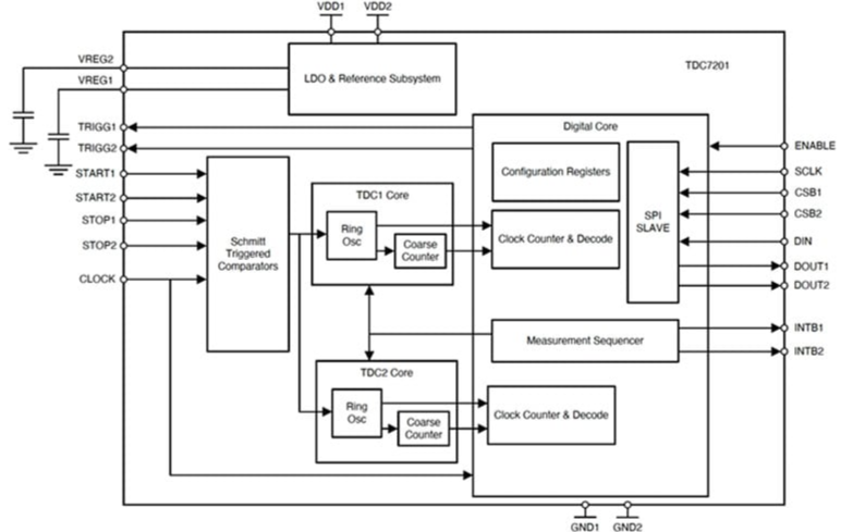
The designer's goal is to simplify the TDC function and save time and space as much as possible. For this reason, the market has launched a highly integrated TDC. For example, Texas Instruments' TDC7201ZAXR (Figure 2) is a dual TDC integrated circuit (IC) designed for automotive ranging applications, such as advanced driver assistance systems (ADAS) using ToF technology. TDC7201ZAXR has two measurement modes: Mode 1 covers 12 to 2000 nanoseconds (ns), while Mode 2 ranges from 250 ns to 8 milliseconds (ms). The time resolution of both modes is 55 picoseconds (ps). This TDC device uses external time, internal ring oscillator, and respective counters to measure the ToF between a universal start pulse and up to six stop pulses.
Figure 2: TDC7201ZAXR functional block diagram shows two TDC cores using independent ring oscillators, coarse counters, external clocks, and clock counters. (Image source: Texas Instruments)
TDC7201ZAXR is powered by a 2 to 3.6 volt DC power supply (VDC). There is an internal low voltage drop regulator that provides stable power to the TDC time base. Schmitt triggers the comparator to adjust and shape the input start and stop signals. The ring oscillator in each TDC is the main time measurement mechanism for each TDC core. The coarse counter is associated with the ring oscillator, while the external clock drives the clock counter. The external clock must have a frequency stable source, as the timing accuracy of TDC directly depends on the clock accuracy. The external clock is the reference for calibrating the time base of the internal ring oscillator. The recommended clock frequency range is 8 to 16 megahertz (MHz) to achieve optimal timing accuracy.
Studying the TDC operating mode helps us understand its working principle. The timing range of Mode 1 is less than 2000 ns, using a ring oscillator output and a coarse counter (Figure 3).