
- 4E, No.3 Shenfeng Road, Liuyao Community, Henggang Street, Longgang District, Shenzhen,China
- cc.shen@xypltd.com
- Call: +86 15112667855
News
How to use advanced digital isolators to optimize isolation and performance
- 2026-09-07
Designers of electronic systems need to isolate power and signals to meet performance requirements and comply with regulatory requirements for user and device safety. Using a transformer can easily achieve isolation of the AC power path. Despite requiring more circuits, the isolation of DC power rails ultimately relies on transformers. However, isolating digitized analog signals and digital serial data streams will face different challenges and complexities.
In this case, the energy transfer technology used for isolation must maintain signal integrity on the isolation barrier to maintain system performance. Although there are many methods to achieve isolation, designers must ensure signal integrity in higher data rates and more challenging environments. Therefore, they are increasingly turning to digital isolators that can transmit data at speeds of 150 megabits per second (Mbps).
This article will briefly explore the reasons for isolation and emphasize the requirements for sensor based circuits. Then, introduce various aspects of using Analog Devices' state-of-the-art digital isolators for isolation and demonstrate how to apply this isolator.
Isolation: Reason and Location
There are multiple reasons why sensor circuits need to be isolated:
Isolation can eliminate common mode voltage variations and minimize certain types of electromagnetic interference (EMI) to the greatest extent possible. Isolation can prevent external noise sources from interfering with the collected signals, thereby ensuring purer and more accurate measurement results. Through isolation, small signals with high common mode voltage can also be measured.
Due to the potential difference between the circuit grounding, the grounding circuit will introduce a voltage difference, resulting in distortion of the measurement signal. Isolation can disconnect the grounding circuit.
The isolation function can prevent dangerous peak voltage, transient voltage, or surge voltage from affecting sensitive measuring components. This can protect the measurement circuit, users, and any connected devices.
The isolation function supports safe level conversion between different circuit functions. The circuit on one side of the isolation barrier can use sensor voltage, while the circuit on the other side can use 3.3 V or 5 V logic level signals.
For example, in high-voltage battery packs, it is usually necessary to understand the voltage of individual cells to ensure safe system operation and extend battery life as much as possible. Despite the presence of common mode voltages of up to several hundred volts in series connected battery packs, it is still necessary to measure the voltage of individual cells.
Although analog circuits and isolation amplifiers can be used to overcome this problem, this method cannot meet the measurement requirements of achieving higher bandwidth and resolution while maintaining system accuracy, linearity, and consistency.
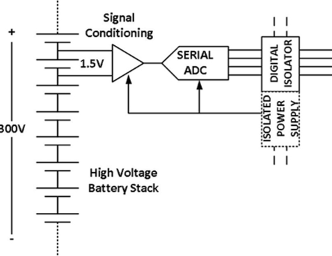
On the contrary, the most accurate, economical, and efficient technique for completing these measurements is to isolate the entire measurement front-end, including the analog-to-digital converter (ADC), and then use an isolated serial link to transmit the digitized data to other parts of the system (Figure 1).
Isolation front-end
Figure 1: When measuring the voltage of a single cell in a high-voltage battery pack, using an isolated front-end can overcome the challenge of common mode voltage. (Image source: Analog Devices)
This method can isolate the common mode voltage of the battery pack and prevent any dangerous high voltage from migrating to the data link side or users in the event of a fault.
Please note that if signal isolation is required, an isolated power supply must be provided, as non isolated power rails will conflict and cancel out signal isolation. The required power isolation can be achieved through an independent power isolation circuit or by using a battery as an independent isolation power source.
How to achieve isolation
Many parameters determine the isolation performance. This includes the maximum voltage that the isolation barrier can withstand before it fails. The relevant regulations stipulate the maximum voltage required, usually several thousand volts, but it depends on the specific application.
There are several different techniques that can be used to achieve isolation of digital signals. This includes capacitive coupling, optical coupling (LED and phototransistor), "micro" scale RF transmission, and magnetic coupling.
The latter is a reliable technology with many advantages, but has always required a relatively large and expensive signal converter. The iCoupler technology introduced by Analog Devices has changed this situation. This method uses chip level primary and secondary coils, and isolates the two through an isolation barrier formed by a polyimide insulation layer (Figure 2). High frequency carriers transmit data to the secondary coil through isolation barriers.