
- 4E, No.3 Shenfeng Road, Liuyao Community, Henggang Street, Longgang District, Shenzhen,China
- cc.shen@xypltd.com
- Call: +86 15112667855
News
How to choose and apply electromechanical relays to achieve multifunctional and reliable signal switching
- 2026-09-30
Applications such as telecommunications and network equipment, automated test equipment (ATE), and security devices increasingly require reliable switching and routing of single or multiple low to medium level DC, AC (analog), and RF signals. Electromechanical relays (EMR) are highly suitable for handling this task.
EMR provides excellent on/off performance and input/output isolation, as well as multi pole configuration, providing flexibility and versatility for designers. In addition, a single relay can support different signal types (AC, DC, low-frequency, RF) in the same device, thereby enhancing its value.
Although EMR has moving parts and physical contacts, due to its long history of application, all its features are readily available. Therefore, they are reliable 'problem solutions' that can be used stably for many years. Although EMR itself is sturdy and durable, designers must choose appropriate relays (coil and contact ratings) and use them correctly to ensure the longest service life.
This article briefly discusses the types and applications of signal relays. Then, taking Omron Electronic Components' products as an example, how to choose and apply EMR was introduced.
Relay types and differences
EMR refers to a type of component with many application specific subtypes. For example, the contact rated current of a power relay is 2 A or higher, while the design contact current of a signal relay is lower than this value.
Signal relays can be divided into two categories: non RF signals and RF signals. Although all relays have basic conduction parameters and maximum values for current and voltage processing, RF relays also have other performance indicators. Specifically, it includes:
Isolation: Even if the contacts are separated, high-frequency signals will leak through the stray capacitance between the contacts. The unit of measurement for isolation is decibels (dB).
Insertion loss: At high frequencies, self inductance, resistance, dielectric loss, and reflection caused by impedance mismatch can all cause signal interference. The unit of measurement for insertion loss is also dB.
Voltage Standing Wave Ratio (VSWR): Generated by constructive/destructive interference between the input signal wave and any reflected signal. This measurement value is an unorganized numerical value, representing the ratio between the maximum waveform value and the minimum waveform value.
Simplify the Bill of Materials
The relay configuration is defined by its number of contacts or poles (P) and the normally open (referring to no power supply)/normally closed contact states (Figure 1). These contacts can be normally open (NO) or normally closed (NC) contacts. The most common are unipolar (SP) and bipolar (DP) configurations, but there are also devices with more contact poles. Throwing (T) refers to the extreme position of the actuator.
Pictures of several EMR contact arrangements and industry standard names
Figure 1: The contact arrangement and industry standard names of several EMRs are shown; The dashed line in Form 2C relay indicates that both armatures have non-conductive links, and when the relay coil receives current, both contacts move simultaneously. (Image source: Sealevel Systems, Inc.)
EMR can support multipole and NO/NC throw, thus simplifying circuits, saving circuit board space, reducing bill of materials (BOM), and lowering costs. The reason is that a relay can switch multiple circuits to fully open, fully closed, or a combination of both, depending on the configuration of poles and throws. The same relay can also switch between AC and DC signals and work simultaneously on multiple circuits.
In some cases, an EMR with an additional pair of poles can be used to power auxiliary circuits, such as supplying power to LED circuits, to indicate to the user that the relay is powered on and has generated the required contact state. In addition, some experienced designers may use double pole double throw (DPDT) relays (SPDT and DPDT relays have the same footprint in many cases) when only single pole double throw (SPDT) devices are needed, providing a "just in case" contact pair to address issues or oversights discovered later in the design cycle.
Omron's G6J-2P-Y DC12 (Figure 2) is an ultra-thin DPDT (Form 2C) relay with a 977 Ω coil, designed for driving voltage and current of 12 V and 12.3 mA, respectively. Please note that other products in this series can provide different coil voltage/current pairings, up to 24 VDC, and are compatible with almost any driving circuit or situation.
Picture of Omron's G6J-2P-Y DC12 ultra-thin DPDT relay
Figure 2: G6J-2P-Y DC12 is an ultra-thin DPDT relay with a 12 V 12.3mA coil; Belonging to relay series products with the same size and contact rating but different coil voltage/current combinations. (Image source: Omron)
The size of this small relay is only 5.7 × 10.6 × 9 mm, making it suitable for use on high-density printed circuit (PC) boards. The G6J-2P-Y DC12 has through-hole terminals, but the same model also offers short surface mount terminals and long surface mount terminals, allowing for maximum flexibility. The rated current of the contacts of this relay and all other relays in this series is 0.3 A at 125 VAC and 1 A at 30 VDC.
Relays and RF
The use of relays is not limited to providing simple "dry" contact closure or processing DC voltage/current and low-frequency AC signals. Some models are specifically designed for ultra-high frequency applications such as ATE.
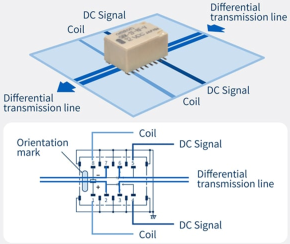
Omron's G6K-2F-RF-V DC4.5 is a miniature surface mount DPDT relay that supports differential transmission signal switching. This 11.7 × 7.9 × 7.1 mm relay has an insertion loss of 3 dB or lower at a frequency of 8 GHz. The relay is still used at higher frequencies, as shown in its eye diagram, and can be used for a 200 mV differential signal with a rise time of 25 ps (Figure 3).