
- 4E, No.3 Shenfeng Road, Liuyao Community, Henggang Street, Longgang District, Shenzhen,China
- cc.shen@xypltd.com
- Call: +86 15112667855
News
How to choose and apply antennas for IoT devices
- 2026-09-28
The surge of Internet of Things (IoT) devices continues to accelerate and inspire the design of innovative end products. However, designers must remember that no matter how much creativity and effort is invested in hardware and software, the crucial role of the antenna cannot be changed. If the antenna cannot work properly, the product performance will be seriously affected.
As the interface between devices and wireless networks, antennas are a crucial part of the design process for IoT devices. This device can convert electrical energy into electromagnetic radio frequency (RF) waves at the transmitter end and convert the received RF signal into electrical energy at the receiver end. Designers can optimize application performance by selecting antennas that meet key engineering parameters. However, numerous available options and considerations may lead to extended design cycles and increased costs.
This article summarizes the role of antennas in wireless IoT devices and briefly introduces the key design criteria that affect antenna selection. Subsequently, taking Amphenol's antenna as an example, the selection of IoT asset trackers, Wi Fi access points (APs), and LoRa IoT devices suitable for low-power Bluetooth (LE) or Wi Fi sensors, GNSS satellite positioning capabilities were explained.
Interpret the specification sheet
The final performance of the antenna depends on engineering decisions, such as installation location and impedance matching network design. To successfully implement, it is necessary to carefully read the specifications of the antenna. The main parameters include:
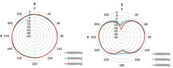
Radiation mode: This parameter graphically defines how the antenna radiates (or absorbs) radio energy in three-dimensional space (Figure 1).
Maximum power transmission: When the transmission line impedance (Z0) matches the antenna impedance (Za), good power transmission can be achieved between the antenna and the receiver. Poor impedance matching can increase return loss (RL). Voltage Standing Wave Ratio (VSWR) represents the impedance matching between the transmission line and the antenna (Table 1). High VSWR values can lead to high power loss. For IoT products, a VSWR below 2 is generally acceptable.
Frequency response: Return loss (RL) depends on the radio frequency. Designers should review the specifications to understand the frequency response of the antenna and ensure that RL is minimized at the predetermined operating frequency (Figure 2).
Directionality: This parameter measures the directional properties of the antenna radiation pattern. The maximum directionality is defined as Dmax.
Efficiency (η): The ratio of total radiated power (TRP or Prad) to input power (Pin), calculated as η=(Prad/Pin) × 100%.
Gain: This parameter describes the amount of power transmitted in the direction of the radiation peak. Usually based on omnidirectional antennas, expressed in units of dBi. The calculation formula is Gainmax=η× Dmax.
A radiation pattern image representing how an antenna radiates through graphics
Figure 1: Represent graphically the radiation pattern of how an antenna radiates or absorbs radio energy in three-dimensional space. The specification sheet usually displays the maximum range of the antenna on the XY and YZ planes when installed as expected. (Image source: Amphenol)
VSWR Return Loss (dB) Power/Voltage Loss%
1 -- --
1.25 -19.1 1.2/11.1
2 -9.5 11.1/33.3
2.5 -7.4 18.2/42.9
3.5 -5.1 30.9/55.5
5 -3.5 44.7/66.6
10 -1.7 67.6/81.8
20 -0.87 81.9/90.5
Table 1: VSWR represents the impedance matching between the transmission line and the antenna. For IoT products, a VSWR below 2 is generally acceptable. (Table source: Steven Keeping)
VSWR and RL depend on the frequency of the image
Figure 2: VSWR and RL depend on frequency. At the predetermined operating frequency, RL should be as small as possible. (Image source: Amphenol)
improve performance
An antenna with poor performance will limit how much electrical energy the transmitter can convert into radiated energy, as well as how much energy the receiver can extract from the received RF signal. Poor performance on either end will narrow the range of the wireless link.
The main factor affecting antenna performance is impedance. A significant mismatch between the impedance of the antenna (related to the voltage and current at the input) and the impedance of the voltage source driving the antenna can lead to poor energy transmission.
A well-designed impedance matching circuit can match the impedance of the transmitter power supply with the impedance of the antenna, thereby minimizing VSWR and subsequent power loss. The impedance of low-power IoT products is usually 50 Ω.
The position of the antenna also greatly affects the transmission power and reception sensitivity of the final product. For built-in antennas, design guidelines recommend placing them at the edge of the printed circuit (PC) board on top of IoT devices and keeping them as far away as possible from other components that may generate electromagnetic interference (EMI) during operation. Except for impedance matching components, which must be located close to the antenna. The solder pads and printed lines connecting the antenna to other circuits on the printed circuit board should be the only copper conductors within the limited clearance area (Figure 3).