
- 4E, No.3 Shenfeng Road, Liuyao Community, Henggang Street, Longgang District, Shenzhen,China
- cc.shen@xypltd.com
- Call: +86 15112667855
News
How to achieve accurate power measurement and management of current detection resistors
- 2026-10-20
The continuous demand for higher energy efficiency and better power management means precise current measurement. This demand spans across various industrial and consumer applications as well as power electronics products, including battery management systems (BMS), switch mode power supplies (SMPS), and motor drives.
Although there are multiple methods to determine power by measuring current, using current sensing resistors (usually referred to as shunt resistors) and differential amplifiers is one of the most suitable and cost-effective solutions technically.
A current sensing resistor is not just a 'resistor' with the required value. To achieve precise detection, the resistor must have high absolute accuracy, excellent dissipation performance that ensures reliability, stable temperature changes even during self heating and environmental temperature changes, and minimize thermoelectric contact effects.
To determine the size of the detection resistor, it is first necessary to assume the maximum acceptable voltage drop (V=IR) at both ends of the current detection resistor at full load current, in order to determine the appropriate resistance value. It is best to set the maximum nominal value of the voltage drop to 100 mV, which is usually a good compromise between factors such as dynamic range, sensitivity, noise, current impedance, and power waste caused by dissipation.
Then, calculate the maximum current flowing through the resistor and determine its maximum value, where R=V/I. In many cases, this value is 1 m Ω or less. By using the selected resistance value and maximum current, the rated dissipation value required for the resistor can be calculated using formula I2R.
Connecting topology is crucial
Equally important, the physical detection layout must be able to minimize voltage measurement errors to the greatest extent possible. Due to the extremely low resistance value and voltage drop, subtle differences in current connection, contact resistance between sensor wires and detection resistors become important considerations.
In a basic two-wire voltage detection device, the current path contact point on the resistor and the voltage connection point on the resistor are the same point (Figure 1, left).
Figure 1: There is a slight but significant difference in the physical connection between the current and voltage contact points between the two-wire sensor (left) and the four wire Kelvin detection (right); The latter can minimize the errors caused by wire loss to the greatest extent possible. (Image source: Wikipedia, modified by the author)
However, when the voltage level across the resistor is low, the obvious dual line layout may affect measurement accuracy. To overcome the relatively small but significant errors caused by the two-wire detection connection, a four wire Kelvin detection connection is usually used (Figure 1, right).
In this topology, the current and voltage detection connections are independent contact points. Although they may appear the same on the electrical connection diagram, they are actually vastly different.
By separating the current contacts, paths, and voltage detection points, four wire detection ensures that the voltage drop between the wire and the current contacts does not affect measurement accuracy. When performing precise readings, this issue becomes particularly prominent when the detected resistance value is roughly the same as the lead resistance value used for measurement.
The four wire detection moves the voltage measurement point near the target impedance, thereby bypassing the voltage drop that may occur in the high current path, greatly reducing this problem.
The correct resistance technology is also important
In addition to having a low resistance of 1 m Ω or less, the detection resistor must also have a low temperature coefficient of resistance (TCR) to prevent drift caused by ambient temperature changes and I2R induced self heating. Therefore, the design, materials, and manufacturing of these resistors are highly specialized.
With the help of Bourns' CSI series metal shunt resistors, designers can meet these requirements. The resistance range of this series of resistors is wide, as small as 0.2 m Ω, and the rated power dissipation can reach up to 15 W (continuous).
These resistors are made of electron beam welding (EBW) resistor material and copper alloy, with two terminal and four terminal options. There are three packaging sizes for the dual terminal model: 5930, 3920, and 2512. The four terminal device is used for more accurate measurement of four wire Kelvin resistance, with a package size of 4026.
Its unique metal alloy current detection component is designed specifically for shunt resistors, with low thermal electromotive force (EMF) and TCR as low as ± 50ppm/° C in the temperature range of+20 ° C to+60 ° C.
Please note that these resistors are manufactured using some material science principles that are contrary to intuition. In any low TCR component, high TCR copper (approximately 3900 ppm/° C) is typically not used. However, copper also has excellent thermal conductivity, so we carefully incorporated copper into the resistor design to improve its power handling performance.
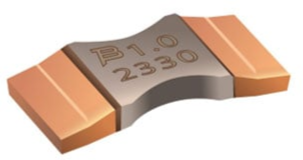
The representative two-wire resistor in the CSI series is CSI2H-2512R-1L00J (Figure 2), which is a 1 m Ω 5 W resistor with a tolerance of ± 5% and a TCR of ± 75 ppm/° C. Other models have even smaller tolerances, at ± 2% or even 1%.